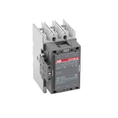
ABB AF210B-30-11-72: A 3-phase contactor for reliable power control. Operates with 48-130 V, AC/DC. Suitable for railway and industrial applications.
Product ModelAF210B-30-11-72
Material Number1SFL517063R7211
Product ID88706
Stock on Request
Last updated: 8/29/2026
Key Features
1
1. Reliable Power Control\"The ABB AF210B-30-11-72 contactor ensures consistent and reliable power control, making it ideal for critical applications in railways and industries.\"
2
2. Wide Voltage Range\"With a wide voltage control range of 48-130 V, AC/DC, this contactor can handle diverse operational requirements, providing flexibility in various settings.\"
3
3. Durable Design\"Built with high-quality materials, the AF210B-30-11-72 contactor is designed to withstand harsh industrial environments and maintain performance over time.\"
4
4. Versatile Applications\"Suitable for railway and industrial applications, this contactor is versatile and can be used in a variety of settings where reliable power control is essential.\"
Technical Specifications
Detailed engineering parameters based on manufacturer documentation
Specifications may be subject to change without notice
Parameter
Value
Parameter
Value
Product Net Width
140 mm
Product Net Depth / Length
180.5 mm
Product Net Height
227 mm
Product Net Weight
5.5 kg
Number of Main Contacts NO
3
Number of Main Contacts NC
0
5
5. Efficient Operation\"The AF210B-30-11-72 contactor operates efficiently, ensuring minimal downtime and maximum productivity in your operations. Its magnetic coil design enhances its performance and reliability.\"
Number of Auxiliary Contacts NO
1
Number of Auxiliary Contacts NC
1
Standards
IEC/EN 60947-1, IEC/EN 60947-4-1, UL 60947-4-1, CSA C22.2 No. 60947-4-1, IEC 60077-1 (applicable parts), IEC 60077-2 (applicable parts), EN 50155 (applicable parts), TR CU 001/2011, IEC 61373, For compliance confirmation on applicable parts based on your application and combination, please consult your ABB sales representatives.
Rated Operational Voltage
Main Circuit 690 V
Conventional Free-air Thermal Current (Ith)
acc. to IEC 60947-4-1, Open Contactors Π= 40 °C 350 A
Rated Operational Current AC-1 (Ie)
(690 V) 40 °C 350 A (690 V) 55 °C 300 A (690 V) 70 °C 240 A
Rated Operational Current AC-3 (Ie)
(415 V) 55 °C 210 A (440 V) 55 °C 210 A (500 V) 55 °C 210 A (690 V) 55 °C 210 A (380 / 400 V) 55 °C 210 A (220 / 230 / 240 V) 55 °C 210
cos phi=0.45 (cos phi=0.35 for Ie > 100 A) at 440 V 2200 A cos phi=0.45 (cos phi=0.35 for Ie > 100 A) at 690 V 2000 A
Maximum Electrical Switching Frequency
(AC-1) 300 cycles per hour (AC-2 / AC-4) 150 cycles per hour (AC-3) 300 cycles per hour
Rated Operational Current DC-1 (Ie)
(110 V) 2 Poles in Series, 40 °C 350 A (220 V) 3 Poles in Series, 40 °C 350 A
Rated Operational Current DC-3 (Ie)
(110 V) 2 Poles in Series, 40 °C 350 A (220 V) 3 Poles in Series, 40 °C 350 A
Rated Operational Current DC-5 (Ie)
(110 V) 2 Poles in Series, 40 °C 350 A (220 V) 3 Poles in Series, 40 °C 350 A
Rated Insulation Voltage (Ui)
acc. to IEC 60947-4-1 and VDE 0110 (Gr. C) 1000 V acc. to UL/CSA 600 V
Rated Impulse Withstand Voltage (Uimp)
Main Circuit 8 kV
Mechanical Durability
5 million
Maximum Mechanical Switching Frequency
300 cycles per hour
Coil Operating Limits
(acc. to IEC 60947-4-1) 0.85 x Uc Min. ... 1.1 x Uc Max. (at θ ⤠70 °C)
Rated Control Circuit Voltage (Uc)
DC Operation 20 ... 60 V
Coil Consumption
Holding at Max. Rated Control Circuit Voltage 50 Hz 10 V·A Holding at Max. Rated Control Circuit Voltage 60 Hz 10 V·A Holding at Max. Rated Control Circuit Voltage DC 2 W Pull-in at Max. Rated Control Circuit Voltage 50 Hz 470 V·A Pull-in at Max. Rated Control Circuit Voltage 60 Hz 470 V·A Pull-in at Max. Rated Control Circuit Voltage DC 520 W
Operate Time
Between Coil De-energization and NC Contact Closing 40 ... 50 ms Between Coil De-energization and NO Contact Opening 43 ... 53 ms Between Coil Energization and NC Contact Opening 45 ... 85 ms Between Coil Energization and NO Contact Closing 50 ... 90 ms
Connecting Capacity Main Circuit
Bar 32 mm² Rigid Al-Cable 2 x 95 ... 120 mm² Rigid Cu-Cable 16 ... 240 mm²
Connecting Capacity Auxiliary Circuit
Flexible with Ferrule 1x 0.75 ... 2.5 mm² Flexible with Insulated Ferrule 2x 0.75 ... 2.5 mm² Flexible 2x0.75 ... 2.5 mm² Solid 2 x 1 ... 4 mm² Stranded 2 x 1 .... 4 mm²
Degree of Protection
acc. to IEC 60529, IEC 60947-1, EN 60529 Coil Terminals IP20 acc. to IEC 60529, IEC 60947-1, EN 60529 Main Terminals IP00
Connecting Terminals (delivered in open position) Main Poles
Flat type c/w screws and bolts
Terminal Type
Main Circuit: Bars
Maximum Operating Voltage UL/CSA
Main Circuit 600 V
General Use Rating UL/CSA
(600 V AC) 300 A
Horsepower Rating UL/CSA
(200 V AC) Three Phase 60 hp (208 V AC) Three Phase 60 hp (220 ... 240 V AC) Three Phase 75 hp (440 ... 480 V AC) Three Phase 150 hp (550 ... 600 V AC) Three Phase 200 hp
Ambient Air Temperature
Close to Contactor Fitted with Thermal O/L Relay (0.85 ... 1.1 Uc) -25 ... 50 °C Close to Contactor without Thermal O/L Relay (0.85 ... 1.1 Uc) -40 ... 70 °C Close to Contactor for Storage -40 ... 70 °C
Maximum Operating Altitude Permissible
Without Derating 3000 m
Resistance to Shock acc. to IEC 60068-2-27
Shock Direction: A 5 g Shock Direction: B1 5 g Shock Direction: B2 5 g Shock Direction: C1 5 g Shock Direction: C2 5 g