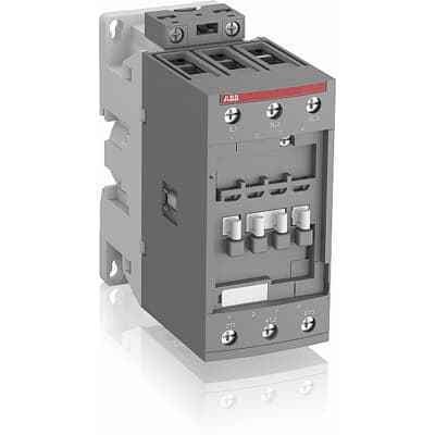
Efficiently control 3-phase motors with the ABB AF65-30-11-12 Line Contactor, featuring electronic coil interface, surge protection, and high operational current.
Product ModelAFC78-30-11-51
Material Number1SBL301001R5111
Product ID88547
Stock on Request
Last updated: 8/29/2026
Key Features
1
1. Electronic Coil InterfaceThe ABB AF65-30-11-12 Line Contactor comes with an electronic coil interface that accepts a wide control voltage range, from 24 to 500 V 50/60 Hz and 20 to 500 V DC, making it versatile for various applications worldwide.
2
2. Built-in Surge SuppressionEquipped with built-in surge protection, this contactor ensures reliable operation and reduces the need for additional surge suppressors, enhancing overall system reliability.
3
3. High Operational CurrentThe contactor supports high operational currents, including 105 A at 690 V AC-1 and 65 A at 220/230/240 V AC-3, making it suitable for a wide range of load requirements.
4
4. Efficient ControlDesigned to manage large control voltage variations, the AF65 series contactors provide efficient control over power circuits up to 690 V AC and 220 V DC, ensuring stable and reliable operation.
Technical Specifications
Detailed engineering parameters based on manufacturer documentation
Specifications may be subject to change without notice
Parameter
Value
Parameter
Value
Product Net Width
67 mm
Product Net Depth / Length
119.5 mm
Product Net Height
111 mm
Product Net Weight
1.02 kg
Number of Main Contacts NO
3
Number of Main Contacts NC
0
5
5. Reduced Panel Energy ConsumptionBy optimizing the control circuit, the ABB AF65-30-11-12 Line Contactor helps reduce panel energy consumption, contributing to a more energy-efficient setup.
Number of Auxiliary Contacts NO
1
Number of Auxiliary Contacts NC
1
Rated Operational Voltage
Main Circuit 690 V
Rated Frequency (f)
Main Circuit 50 / 60 Hz
Conventional Free-air Thermal Current (Ith)
acc. to IEC 60947-4-1, Open Contactors Π= 40 °C 105 A acc. to IEC 60947-5-1, Π= 40 °C 16 A
Rated Operational Current AC-1 (Ie)
(690 V) 40 °C 105 A (690 V) 60 °C 90 A (690 V) 70 °C 80 A
Rated Operational Current AC-3 (Ie)
(415 V) 60 °C 80 A (440 V) 60 °C 70 A (380 / 400 V) 60 °C 80 A (220 / 230 / 240 V) 60 °C 80 A
Rated Operational Current AC-3e (Ie)
(400 V) 60 °C 80 A (415 V) 60 °C 70 A (380 / 400 V) 60 °C 80 A (220 / 230 / 240 V) 60 °C 80 A
Rated Short-time Withstand Current Low Voltage (Icw)
at 40 °C Ambient Temp, in Free Air, from a Cold State 15 min 110 A at 40 °C Ambient Temp, in Free Air, from a Cold State 1 min 250 A at 40 °C Ambient Temp, in Free Air, from a Cold State 1 s 1000 A at 40 °C Ambient Temp, in Free Air, from a Cold State 30 s 350 A
Maximum Breaking Capacity
cos phi=0.45 (cos phi=0.35 for Ie > 100 A) at 440 V 950 A cos phi=0.45 (cos phi=0.35 for Ie > 100 A) at 690 V 600 A
Maximum Electrical Switching Frequency
(AC-1) 600 cycles per hour (AC-2 / AC-4) 150 cycles per hour (AC-3) 1200 cycles per hour
Rated Insulation Voltage (Ui)
acc. to IEC 60947-4-1 and VDE 0110 (Gr. C) 690 V acc. to UL/CSA 600 V
Rated Impulse Withstand Voltage (Uimp)
Auxiliary Circuit 6 kV
Maximum Mechanical Switching Frequency
3600 cycles per hour
Coil Consumption
Average Holding Value 50 / 60 Hz 20 V·A Average Pull-in Value 50 Hz 150 V·A Average Pull-in Value 60 Hz 151 V·A
Operate Time
Between Coil De-energization and NC Contact Closing 6 ... 19 ms Between Coil De-energization and NO Contact Opening 4 ... 14 ms Between Coil Energization and NC Contact Opening 3 ... 16 ms Between Coil Energization and NO Contact Closing 7 ... 21 ms
Mounting on DIN Rail
TH35-15 (35 x 15 mm Mounting Rail) acc. to IEC 60715 TH35-7.5 (35 x 7.5 mm Mounting Rail) acc. to IEC 60715
acc. to IEC 60529, IEC 60947-1, EN 60529 Auxiliary Terminals IP20 acc. to IEC 60529, IEC 60947-1, EN 60529 Coil Terminals IP20 acc. to IEC 60529, IEC 60947-1, EN 60529 Main Terminals IP10
Terminal Type
Screw Terminals
Maximum Operating Voltage UL/CSA
Main Circuit 600 V
General Use Rating UL/CSA
(600 V AC) 90 A
Horsepower Rating UL/CSA
(120 V AC) Single Phase 5 hp (200 ... 208 V AC) Three Phase 25 hp (220 ... 240 V AC) Three Phase 30 hp (240 V AC) Single Phase 7-1/2 hp (440 ... 480 V AC) Three Phase 60 hp
Tightening Torque UL/CSA
Control Circuit 11 in·lb Main Circuit 35 in·lb
Ambient Air Temperature
Close to Contactor without Thermal O/L Relay -40 ... 70 °C Close to Contactor for Storage -60 ... +80 °C Near Contactor for Operation in Free Air (0.85 ... 1.1 Uc) -40 ... +60 °C Near Contactor for Operation in Free Air (Uc) -40 ... 70 °C
Climatic Withstand
Category B according to IEC 60947-1 Annex Q
Maximum Operating Altitude Permissible
Without Derating 3000 m
Resistance to Shock acc. to IEC 60068-2-27
Closed, Shock Direction: A 25 g Closed, Shock Direction: B1 25 g Closed, Shock Direction: B2 15 g Closed, Shock Direction: C1 25 g Closed, Shock Direction: C2 25 g Open, Shock Direction: B1 5 g