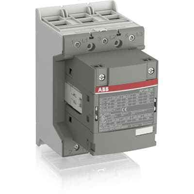
ABB AF140-30-00-12: A 3-phase contactor for motor starting, isolation, bypass, and distribution. Operates with 48-130 VAC/VDC, 200 A at 690 V, and 500,000 operating cycles.
Product ModelAF140-30-00-12
Material Number1SFL447001R1200
Product ID85607
Stock on Request
Last updated: 8/29/2026
Key Features
1
1. Versatile ApplicationsThe ABB AF140-30-00-12 is suitable for various applications including motor starting, isolation, bypass, and distribution up to a maximum voltage of 690 V.
2
2. Wide Control Voltage RangeThis contactor operates with a wide control voltage range of 48-130 VAC/VDC, ensuring flexibility in different electrical systems.
3
3. High ReliabilityDesigned with high reliability in mind, the AF140-30-00-12 can withstand short voltage dips and voltage sags, ensuring consistent performance.
4
4. Durable DesignWith a mechanical durability of 5 million operating cycles, this contactor is built to last and provides long-term reliability in demanding electrical environments.
5
Technical Specifications
Detailed engineering parameters based on manufacturer documentation
Specifications may be subject to change without notice
Parameter
Value
Parameter
Value
Product Net Width
90 mm
Product Net Depth / Length
126 mm
Product Net Height
150 mm
Product Net Weight
1.55 kg
Number of Main Contacts NO
3
Number of Main Contacts NC
0
5. Compact and EfficientThe AF140-30-00-12 features a compact design that reduces panel energy consumption. It also includes built-in surge suppression and add-on auxiliary contact blocks for side mounting and a wide range of accessories.
Number of Auxiliary Contacts NO
0
Number of Auxiliary Contacts NC
0
Rated Operational Voltage
Main Circuit 690 V
Rated Frequency (f)
Main Circuit 50 / 60 Hz
Conventional Free-air Thermal Current (Ith)
acc. to IEC 60947-4-1, Open Contactors Π= 40 °C 200 A
Rated Operational Current AC-1 (Ie)
(690 V) 40 °C 200 A (690 V) 70 °C 160 A
Rated Operational Current AC-3 (Ie)
(415 V) 55 °C 140 A (440 V) 55 °C 140 A (500 V) 55 °C 130 A (690 V) 55 °C 80 A (380 / 400 V) 55 °C 140 A (220 / 230 / 240 V) 55 °C 140 A
Rated Operational Current AC-3e (Ie)
(415 V) 60 °C 140 A (440 V) 60 °C 140 A (500 V) 60 °C 130 A (690 V) 60 °C 80 A (380 / 400 V) 60 °C 140 A (220 / 230 / 240 V) 60 °C 140 A
Rated Short-time Withstand Current Low Voltage (Icw)
at 40 °C Ambient Temp, in Free Air, from a Cold State 10 s 1168 A at 40 °C Ambient Temp, in Free Air, from a Cold State 15 min 200 A at 40 °C Ambient Temp, in Free Air, from a Cold State 1 min 477 A at 40 °C Ambient Temp, in Free Air, from a Cold State 1 s 1460 A at 40 °C Ambient Temp, in Free Air, from a Cold State 30 s 674 A
Maximum Breaking Capacity
cos phi=0.45 (cos phi=0.35 for Ie > 100 A) at 440 V 3000 A cos phi=0.45 (cos phi=0.35 for Ie > 100 A) at 690 V 1500 A
Maximum Electrical Switching Frequency
(AC-1) 300 cycles per hour (AC-2 / AC-4) 150 cycles per hour (AC-3) 300 cycles per hour
Rated Operational Current DC-1 (Ie)
(110 V) 2 Poles in Series, 40 °C 160 A (220 V) 3 Poles in Series, 40 °C 160 A
Rated Operational Current DC-3 (Ie)
(110 V) 2 Poles in Series, 40 °C 160 A (220 V) 3 Poles in Series, 40 °C 160 A
Rated Operational Current DC-5 (Ie)
(110 V) 2 Poles in Series, 40 °C 160 A (220 V) 3 Poles in Series, 40 °C 160 A
Rated Insulation Voltage (Ui)
acc. to IEC 60947-4-1 and VDE 0110 (Gr. C) 1000 V acc. to UL/CSA 600 V
Rated Impulse Withstand Voltage (Uimp)
Main Circuit 8 kV
Mechanical Durability
5 million
Maximum Mechanical Switching Frequency
300 cycles per hour
Coil Operating Limits
(acc. to IEC 60947-4-1) 0.85 x Uc Min. ... 1.1 x Uc Max. (at θ ⤠70 °C)
Rated Control Circuit Voltage (Uc)
50 Hz 48 ... 130 V 60 Hz 48 ... 130 V DC Operation 48 ... 130 V
Coil Consumption
Holding at Max. Rated Control Circuit Voltage 50 Hz 4 V·A Holding at Max. Rated Control Circuit Voltage 60 Hz 4 V·A Holding at Max. Rated Control Circuit Voltage DC 2.5 W Pull-in at Max. Rated Control Circuit Voltage 50 Hz 180 V·A Pull-in at Max. Rated Control Circuit Voltage 60 Hz 180 V·A Pull-in at Max. Rated Control Circuit Voltage DC 150 W
Operate Time
Between Coil De-energization and NO Contact Opening 37 ... 47 ms Between Coil Energization and NO Contact Closing 25 ... 55 ms
Connecting Capacity Main Circuit
Flexible 2 x 10 ... 70 mm² Rigid Cu-Cable 1 x 10 ... 95 mm²
Connecting Capacity Auxiliary Circuit
Flexible with Ferrule 2x 0.75 ... 2.5 mm² Flexible with Insulated Ferrule 2x 0.75 ... 2.5 mm² Flexible 2x0.75 ... 2.5 mm² Solid 2 x 1 ... 4 mm² Stranded 2 x 1 .... 4 mm²
Degree of Protection
acc. to IEC 60529, IEC 60947-1, EN 60529 Coil Terminals IP20 acc. to IEC 60529, IEC 60947-1, EN 60529 Main Terminals IP00
Terminal Type
Double Clamp
NEMA Size
4
Continuous Current Rating NEMA
135 A
Horsepower Rating NEMA
(200 V AC) Three Phase 40 Hp (230 V AC) Three Phase 50 Hp (460 V AC) Three Phase 100 Hp (575 V AC) Three Phase 100 Hp
Maximum Operating Voltage UL/CSA
Main Circuit 600 V
General Use Rating UL/CSA
(600 V AC) 200 A
Horsepower Rating UL/CSA
(200 V AC) Three Phase 40 hp (208 V AC) Three Phase 40 hp (220 ... 240 V AC) Three Phase 50 hp (440 ... 480 V AC) Three Phase 100 hp (550 ... 600 V AC) Three Phase 125 hp
Ambient Air Temperature
Close to Contactor Fitted with Thermal O/L Relay (0.85 ... 1.1 Uc) -25 ... 50 °C Close to Contactor without Thermal O/L Relay (0.85 ... 1.1 Uc) -40 ... 70 °C Close to Contactor for Storage -40 ... 70 °C