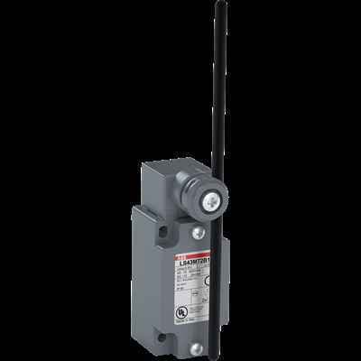
"ABB LS45M72B11: 40 mm wide, zinc alloy limit switch with 4 mounting holes, suitable for applications up to 600 V."
Product ModelLS45M72B11
Material Number1SBV013172R1211
Product ID76397
Stock on Request
Last updated: 8/29/2026
Key Features
1
1. Reliability and Durability\"Made from zinc alloy material, the ABB LS45M72B11 is designed to withstand harsh environments and ensure reliable performance in your electrical control systems.\"
2
2. Versatile Mounting Options\"With 4 mounting holes, the LS45M72B11 offers flexible installation options, making it easy to integrate into various applications.\"
3
3. High Voltage Capability\"Capable of handling up to 600 V, this limit switch is suitable for a wide range of electrical control systems.\"
4
4. Durable Construction\"The polyamide roller lever ensures smooth operation and long-lasting performance, reducing the need for frequent replacements.\"
5
Technical Specifications
Detailed engineering parameters based on manufacturer documentation
Specifications may be subject to change without notice
Parameter
Value
Parameter
Value
Product Net Width
40 mm
Product Net Height
195 mm
Product Net Depth / Length
60 mm
Product Net Weight
0.272 kg
Action Type of the Contact Element (acc. to IEC 60947-5-1)
Snap action contacts
Actuation Speed
acc. to IEC 60947-5-1 Max. 1.5 m/s
5. Standardized Design\"Compliant with IEC 60947-5-1 and VDE 0110 (Gr. C) standards, the LS45M72B11 meets industry requirements for safety and reliability.\"
Actuation Torque
acc. to IEC 60947-5-1 Min. 0.15 N·m
Actuator Type
addjustable à 6 mm polyamide rod lever
Angular Head Adjustment
adjustable head every 90°
Angular Lever Adjustment
9° in 9°
B10d Value
Operations 50 Millions
Climatic Withstand
according to IEC 68-2-3 and salty mist according to IEC 68-2-11
Conventional Free-air Thermal Current (Ith)
acc. to IEC 60947-5-1, Π= 40 °C 10 A
Connecting Capacity
Bar AWG 20 ... AWG 14 mm² Bar 0.5 ... 2.5 mm²
Consistency (Measured over 1 Million Operations)
0.05 mm
Contact Element Form (acc. to IEC 60947-5-1)
Zb
Connecting Terminals (delivered in open position)
M3.5 (+,-) pozidriv 2 screw with cable clamp
Degree of Protection
acc. to IEC 60529 IP66
Electrical Shock Protection acc. to IEC 536
Class I
Housing Material
Metal
Maximum Electrical Switching Frequency
3600 cycles per hour (AC-15) 3600 cycles per hour (DC-13) 3600 cycles per hour
Maximum Mounted Auxiliary Contacts
1 NO, 1 NC
Mechanical Durability
25 million
Mounting Type
40 mm (EN 50041)
Mounting by Screws (not supplied)
2 or 4 x M5 screws
Movement to be Detected
Fully Directional Translation Movement
Number of Auxiliary Contacts NC
1
Number of Auxiliary Contacts NO
1
Number and Type of Bottom Cable Glands
1/2 NPT cable gland
Operating Head Shape
D shape acc. EN 50041
Pilot Duty UL/CSA
A600 Q600
Positive Opening Operation of NC Contact(s)
No
Rated Impulse Withstand Voltage (Uimp)
6 kV
Rated Operational Current AC-15 (Ie)
(230 V AC) 3.1 A (400 V) NC 4 (24 V) 10 A (130 V) 5.5 A (240 V) 3 A
Rated Frequency (f)
Supply Circuit 50 / 60 Hz
Rated Insulation Voltage (Ui)
acc. to IEC 60947-5-1 and VDE 0110 (Gr. C) 500 V acc. to UL/CSA 600 V
Rated Operational Current DC-13 (Ie)
(24 V) 6 A (110 V) 0.6 A (125 V) 0.55 A (250 V) 0.4 A
Resistance Between Contacts
25 ms
Short-Circuit Protective Devices
gG Type Fuses 10 A
Terminal Marking
according to EN 50013
Terminal for Protective Conductor
M 3.5 (+,-) pozidriv 2 screw with cable clamp
Ambient Air Temperature
Operation -25 ... +70 °C Storage -30 ... +80 °C
Resistance to Shock acc. to IEC 60068-2-27
Half-sine Pulse for 11 ms, No Change in Contact Position 50 m/s²
Resistance to Vibrations
No Change in Position of Contacts Greater than 100 µs: 25g 10 ... 500 Hz