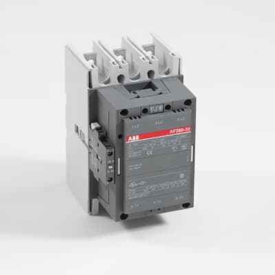
Compact, reliable, and easy to maintain, the ABB AF260-30-11-70 is perfect for controlling power circuits with its built-in surge protection and wide voltage range.
Product ModelAF260-30-00-70
Material Number1SFL537001R7000
Product ID73295
Stock on Request
Last updated: 8/29/2026
Key Features
1
1. Compact DesignThe AF260-30-11-70 boasts a reduced width, making it ideal for space-saving applications. Its compact size allows for more efficient panel designs and reduced energy consumption.
2
2. Reliable OperationDesigned for all networks, this contactor ensures reliable operation over an extended voltage range of 85 to 110% of the rated control voltage. It is also equipped with built-in surge suppression for added safety.
3
3. Easy MaintenanceThe contactor features easy-to-use accessories and allows for coil terminal access in the front, making maintenance tasks straightforward. The main contacts and coil can be inspected and maintained with ease.
4
4. Versatile Voltage RangeThe AF260-30-11-70 operates effectively within a wide voltage range of 100-250V AC/DC, making it compatible with various global standards. This versatility simplifies logistics and reduces the need for multiple coils.
Technical Specifications
Detailed engineering parameters based on manufacturer documentation
Specifications may be subject to change without notice
Parameter
Value
Parameter
Value
Product Net Width
140 mm
Product Net Depth / Length
180.5 mm
Product Net Height
227 mm
Product Net Weight
5.05 kg
Number of Main Contacts NO
3
Number of Main Contacts NC
0
5
5. Positive Safety FeaturesThe contactor ensures positive safety between its auxiliary contact blocks, providing a secure operation environment. It also includes mechanically-linked auxiliary contacts compliant with international safety standards.
Number of Auxiliary Contacts NO
0
Number of Auxiliary Contacts NC
0
Rated Operational Voltage
Main Circuit 690 V
Rated Frequency (f)
Main Circuit 50 / 60 Hz
Conventional Free-air Thermal Current (Ith)
acc. to IEC 60947-4-1, Open Contactors Π= 40 °C 400 A
Rated Operational Current AC-1 (Ie)
(690 V) 40 °C 400 A (690 V) 55 °C 350 A (690 V) 70 °C 290 A
Rated Operational Current AC-3 (Ie)
(415 V) 55 °C 260 A (440 V) 55 °C 240 A (500 V) 55 °C 240 A (690 V) 55 °C 220 A (380 / 400 V) 55 °C 260 A (220 / 230 / 240 V) 55 °C 260
Rated Short-time Withstand Current Low Voltage (Icw)
at 40 °C Ambient Temp, in Free Air, from a Cold State 10 s 2400 A at 40 °C Ambient Temp, in Free Air, from a Cold State 15 min 500 A at 40 °C Ambient Temp, in Free Air, from a Cold State 1 min 1100 A at 40 °C Ambient Temp, in Free Air, from a Cold State 1 s 3500 A at 40 °C Ambient Temp, in Free Air, from a Cold State 30 s 1500 A
Maximum Breaking Capacity
cos phi=0.45 (cos phi=0.35 for Ie > 100 A) at 440 V 2600 A cos phi=0.45 (cos phi=0.35 for Ie > 100 A) at 690 V 2400 A
Maximum Electrical Switching Frequency
300 cycles per hour (AC-1) 300 cycles per hour (AC-2 / AC-4) 150 cycles per hour (AC-3) 300 cycles per hour
Rated Operational Current DC-1 (Ie)
(110 V) 2 Poles in Series, 40 °C 400 A (220 V) 3 Poles in Series, 40 °C 400 A
Rated Operational Current DC-3 (Ie)
(110 V) 2 Poles in Series, 40 °C 400 A (220 V) 3 Poles in Series, 40 °C 400 A
Rated Operational Current DC-5 (Ie)
(110 V) 2 Poles in Series, 40 °C 400 A (220 V) 3 Poles in Series, 40 °C 400 A
Rated Insulation Voltage (Ui)
acc. to IEC 60947-4-1 and VDE 0110 (Gr. C) 1000 V acc. to UL/CSA 600 V
Rated Impulse Withstand Voltage (Uimp)
Main Circuit 8 kV
Mechanical Durability
5 million
Maximum Mechanical Switching Frequency
300 cycles per hour
Coil Operating Limits
(acc. to IEC 60947-4-1) 0.85 x Uc Min. ... 1.1 x Uc Max. (at θ ⤠70 °C)
Rated Control Circuit Voltage (Uc)
50 Hz 100 ... 250 V 60 Hz 100 ... 250 V DC Operation 100 ... 250 V
Coil Consumption
Holding at Max. Rated Control Circuit Voltage 50 Hz 10 V·A Holding at Max. Rated Control Circuit Voltage 60 Hz 10 V·A Holding at Max. Rated Control Circuit Voltage DC 2 W Pull-in at Max. Rated Control Circuit Voltage 50 Hz 470 V·A Pull-in at Max. Rated Control Circuit Voltage 60 Hz 470 V·A Pull-in at Max. Rated Control Circuit Voltage DC 520 W
Operate Time
Between Coil De-energization and NC Contact Closing 40 .... 50 ms Between Coil De-energization and NO Contact Opening 43 ... 53 ms Between Coil Energization and NC Contact Opening 45 ... 85 ms Between Coil Energization and NO Contact Closing 50 ... 90 ms
Connecting Capacity Main Circuit
Bar 32 mm² Rigid Al-Cable 2 x 95 ... 120 mm² Rigid Cu-Cable 16 ... 240 mm²
Connecting Capacity Auxiliary Circuit
Flexible with Ferrule 2x 0.75 ... 2.5 mm² Flexible with Insulated Ferrule 1x 0.75 ... 2.5 mm² Flexible 2x0.75 ... 2.5 mm² Solid 2 x 1 ... 4 mm² Stranded 2 x 1 .... 4 mm²
Degree of Protection
acc. to IEC 60529, IEC 60947-1, EN 60529 Coil Terminals IP20 acc. to IEC 60529, IEC 60947-1, EN 60529 Main Terminals IP00
Terminal Type
Main Circuit: Bars
NEMA Size
5
Maximum Operating Voltage UL/CSA
Main Circuit 600 V
General Use Rating UL/CSA
(600 V AC) 350 A
Horsepower Rating UL/CSA
(200 V AC) Three Phase 75 hp (208 V AC) Three Phase 75 hp (220 ... 240 V AC) Three Phase 100 hp (440 ... 480 V AC) Three Phase 200 hp (550 ... 600 V AC) Three Phase 250 hp
Ambient Air Temperature
Close to Contactor Fitted with Thermal O/L Relay (0.85 ... 1.1 Uc) -25 ... 50 °C Close to Contactor without Thermal O/L Relay (0.85 ... 1.1 Uc) -40 ... 70 °C Close to Contactor for Storage -40 ... 70 °C
Maximum Operating Altitude Permissible
Without Derating 3000 m
Resistance to Shock acc. to IEC 60068-2-27
Shock Direction: A 5 g Shock Direction: B1 5 g Shock Direction: B2 5 g Shock Direction: C1 5 g Shock Direction: C2 5 g