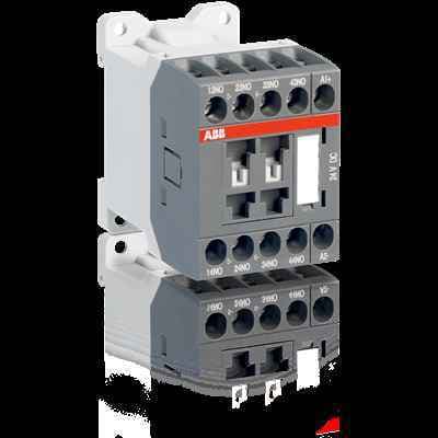
ABB NSL40E-81: 24VDC, 6A, 4P contactor relay for switching auxiliary and control circuits. Ideal for industrial applications with spring terminals and long-lasting performance.
Product ModelNSL40E-81
Material Number1SBH103001R8140
Product ID69874
Stock on Request
Last updated: 8/29/2026
Key Features
1
1. Reliable OperationThe ABB NSL40E-81 contactor relay is designed to provide reliable operation in a variety of industrial settings. Its robust construction ensures consistent performance even under demanding conditions.
2
2. Versatile ApplicationThis contactor relay is versatile and can be used for switching both auxiliary and control circuits. Its flexibility makes it an essential component in many industrial control systems.
3
3. Efficient Power ManagementWith a 6A amperage rating, the NSL40E-81 efficiently manages power distribution in your system. This makes it suitable for applications requiring precise control over electrical currents.
4
4. Easy InstallationThe NSL40E-81 features spring terminals, making installation straightforward and hassle-free. This reduces downtime and ensures that your system is up and running quickly.
Technical Specifications
Detailed engineering parameters based on manufacturer documentation
Specifications may be subject to change without notice
Parameter
Value
Parameter
Value
Product Net Width
45 mm
Product Net Depth / Length
72.5 mm
Product Net Height
68 mm
Product Net Weight
0.28 kg
Number of Auxiliary Contacts NO
4
Number of Auxiliary Contacts NC
0
5
5. Long-Lasting PerformanceBuilt with high-quality components, the ABB NSL40E-81 contactor relay offers long-lasting performance. Its durability ensures that it will continue to operate effectively over an extended period, reducing the need for frequent replacements.
Standards
IEC 60947-5-1 and EN 60947-5-1, UL 508, CSA C22.2 N°14
Rated Operational Voltage
Auxiliary Circuit 690 V Main Circuit 690 V
Rated Frequency (f)
Auxiliary Circuit 50 / 60 Hz
Conventional Free-air Thermal Current (Ith)
acc. to IEC 60947-5-1, Π= 40 °C 10 A
Rated Operational Current AC-15 (Ie)
(500 V) NC 2 (500 V) 2 A (690 V) 2 A (24 / 127 V) 6 A (220 / 240 V) 4 A (400 / 440 V) 3 A
Rated Short-time Withstand Current Low Voltage (Icw)
for 0.1 s 140 A for 1 s 100 A
Maximum Electrical Switching Frequency
(AC-15) 1200 cycles per hour (DC-13) 900 cycles per hour
Rated Operational Current DC-13 (Ie)
(24 V) 6 A / 144 W (48 V) 2.8 A / 134 W (72 V) 1 A / 72 W (110 V) 0.55 A / 60 W (125 V) 0.55 A / 69 W (220 V) 0.27 A / 60 W (250 V) 0.27 A / 68 W
Rated Insulation Voltage (Ui)
acc. to IEC 60947-5-1 and VDE 0110 (Gr. C) 690 V acc. to UL/CSA 600 V
Rated Impulse Withstand Voltage (Uimp)
Auxiliary Circuit 6 kV
Maximum Mechanical Switching Frequency
3600 cycles per hour
Rated Control Circuit Voltage (Uc)
DC Operation 24 V
Operate Time
Between Coil De-energization and NC Contact Closing 15 ... 20 ms Between Coil De-energization and NO Contact Opening 13 ... 17 ms Between Coil Energization and NC Contact Opening 31 ... 53 ms Between Coil Energization and NO Contact Closing 36 ... 59 ms
acc. to IEC 60529, IEC 60947-1, EN 60529 Auxiliary Terminals IP20 acc. to IEC 60529, IEC 60947-1, EN 60529 Coil Terminals IP20
Terminal Type
Screw Terminals
Tightening Torque UL/CSA
Auxiliary Circuit 9 in·lb Control Circuit 9 in·lb
Ambient Air Temperature
Close to Contactor for Storage -60 ... +80 °C Near Contactor for Operation in Free Air -40 ... 70 °C
Climatic Withstand
Category B according to IEC 60947-1 Annex Q
Maximum Operating Altitude Permissible
Without Derating 3000 m
Resistance to Shock acc. to IEC 60068-2-27
Closed, Shock Direction: A 20 g Closed, Shock Direction: B1 15 g Closed, Shock Direction: C1 19 g Closed, Shock Direction: C2 14 g Open, Shock Direction: A 10 g Open, Shock Direction: B1 5 g Open, Shock Direction: C1 8 g Open, Shock Direction: C2 8 g Shock Direction: B2 10 g
Resistance to Vibrations
3g Closed Position & 2g Open Position 5 ... 300 Hz