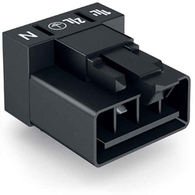
Angled 4-pole plug for PCBs with Cod. A, made from Polyamide (PA66) and chrome nickel spring steel, suitable for general mains applications.
Product Model890-814/011-000
Product ID50286
Stock on Request
Last updated: 8/29/2026
Key Features
1
FeatureSecure and reliable connections with Cod. A coding
2
FeatureAngled design for easy installation on PCBs
3
FeatureDurable construction with Polyamide (PA66) and chrome nickel spring steel
4
FeatureSuitable for a wide temperature range (-35 … +85 °C)
5
FeatureCompliant with various international standards and certifications (e.g., EN 61535, ABS, DNV GL)
Technical Specifications
Detailed engineering parameters based on manufacturer documentation
Specifications may be subject to change without notice
Parameter
Value
Parameter
Value
Total number of potentials
4
Number of levels
1
PE function
Preceding PE contact
Pin spacing
4.4 mm / 0.173 inches
Width
19.2 mm / 0.756 inches
Height
15.7 mm / 0.618 inches
Height from the surface
12.2 mm / 0.48 inches
Depth
28.4 mm / 1.118 inches
Solder pin length
3.5mm
Solder pin dimensions
1 x 0.8 mm
Drilled hole diameter with tolerance
1.3(+0.1)mm
Use
General mains applications
Coding
A
Variable coding
No
Marking
1/L' 2/L ⏚ N
Potential Marking
1/L' 2/L ⏚ N
Mating force of a plug-in connection
approx. 20 70 N (depending on pole number)
Retention force of a plug-in connection
Locked: > 80 N
Unmating force of a plug-in connection
Unlocked: approx. 20 70 N (depending on pole number)
Number of mating cycles
200, without resistive load
Design
angled
Contact type (pluggable connector)
Male connector/plug
Connector (connection type)
for PCB
Mismating protection
Yes
Note on mismating protection
All WINSTA® components are 100% protected against mismating when:a.) plugging different numbers of polesb.) plugging while rotated 180c.) plugging while laterally staggeredd.) plugging one pole
Mating direction to the PCB
0°
Locking lever
yes
Locking of plug-in connection
locking lever
Note on locking system
All connectors for mounted installations (snap-in versions for lighting fixtures or devices, all types of PCB and distribution connectors) are factory-equipped with locking levers to ensure plugs and sockets are securely locked. Additional locking levers are only required for flying leads (plug/socket).
PCB contact
THT
Solder pin arrangement
2 in-line solder pins/pole
Number of solder pins per potential
2
Note (material data)
Information on material specifications can be found here
Some versions may also be used for current interruption in accordance with the UL certificate in select applications with currents below 5 A and voltages up to 600 V. For further information, please contact your local sales office.