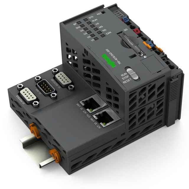
The WAGO PFC200 Controller, 2nd Generation, features a Cortex A8 1GHz processor, multiple interfaces, and high program memory for advanced automation.
Product Model750-8216/040-000
Product ID44904
Stock on Request
Last updated: 8/29/2026
Key Features
1
FeatureHigh-Performance Processing
2
FeatureMultiple Interfaces
3
FeatureAdvanced Program Memory
4
FeatureRobust Protection
5
FeatureCompatibility with CODESYS
Technical Specifications
Detailed engineering parameters based on manufacturer documentation
Specifications may be subject to change without notice
Parameter
Value
Parameter
Value
Communications
PROFIBUS
ETHERNET protocols
DHCP
Telecontrol protocols
IEC 60870 (additional license as slave or master)
Visualization
Web-Visu
Operating system
Real-time Linux (with PREEMPT_RT patch)
CPU
Cortex A8; 1 GHz
Programming languages per IEC 61131-3
Instruction List (IL)
Programming environment
CODESYS V3.5, Firmware Release 23 or higher
Configuration options
CODESYS V3
Transmission rate
ETHERNET: 10/100 mbit/s
Transmission medium (communication/fieldbus)
ETHERNET: Twisted Pair S-UTP; 100 Ω; Cat. 5; 100 m maximum cable length
Main memory (RAM)
512MB
Internal memory (flash)
4096MB
Non-volatile hardware memory
128Kbytes
Program memory
CODESYS V2: 16 mB; CODESYS V3: 32 mB
Data memory
CODESYS V2: 64 mB; CODESYS V3: 128 mB
Non-volatile software memory
128.Kbytes
Type of memory card
SD card
Memory card slot
Push-push mechanism; Cover lid (sealable)
Number of modules per node (max.)
64
Number of modules without a bus extension (max.)
64
Input and output process image (internal) max.
1000 Words/1000 Words
Input and output process image (Modbus®) max.
CODESYS V2: 1000 Words/1000 Words; CODESYS V3: 32000 Words/32000 Words
Input and output process image (PROFIBUS) max.
244 bytes/244 bytes
Input and output process image (CAN) max.
2000 Words/2000 Words
Indicators
LED (SYS, RUN, I/O, CAN, BF, DIA, U1 U4) red/green/orange: Status system, program, internal data bus, CANopen, PROFIBUS, PROFIBUS diagnostics, status programmable by user (can be used via CODESYS library); LED (A, B) green: System power supply status, field supply
Derating
Derating (supply voltage):Ambient temperatures under laboratory conditions: (?25 +30°%);for ?40 +55掳°C: 24掳V (?25 +20°%);for +55 +70°°C: 24掳V (?25 +10°%);Lower limit in all temperature ranges: ?27.5°% (including 15°% residual ripple)
Supply voltage (system)
24 VDC; Via pluggable connector (CAGE CLAMP® connection); Derating must be observed!
Input current (typ.) at nominal load (24 V)
550mA
Total current (system supply)
1,700mA
Supply voltage (field)
24 VDC;?Power supply via pluggable connector (CAGE CLAMP® connection); Transmission via power jumper contacts; Derating must be observed!
Current carrying capacity (power jumper contacts)
10A
Number of outgoing power jumper contacts
2
Rated surge voltage
1 kV
Connection technology: communication/fieldbus
PROFIBUS: 1 x D-sub 9 socket; CANopen: 1 x D-sub 9 plug; modbus (TCP, UDP): 2 x RJ-45; modbus RTU: 1 x D-sub 9 socket; RS-232 serial interface: 1 x D-sub 9 socket; RS-4852 interface: 1 x D-sub 9 socket
Connection technology: system supply
2 x CAGE CLAMP®
Connection technology: field supply
4 x CAGE CLAMP®
Connection type 1
System/field supply
Solid conductor
0.25 2.5 m㎡/ 24 14 AWG
Fine-stranded conductor
0.25 2.5 m㎡/ 24 14 AWG
Strip length
8 9 mm / 0.31 0.35 inches
Connection technology: device configuration
1 x Male connector; 4-pole
Width
112 mm / 4.409 inches
Height
100 mm / 3.937 inches
Depth
71.9 mm / 2.831 inches
Depth from upper-edge of DIN-rail
64.7 mm / 2.547 inches
Weight
260.8g
Housing material
Polycarbonate; polyamide 6.6
Conformity marking
CE
Ambient temperature (operation)
-40 … +70 °C
Ambient temperature (storage)
-40 … 85 °C
Protection type
IP20
Pollution degree
2 per IEC 61131-2
Operating altitude
Without temperature derating: 0 2000 m; with temperature derating: 2000 5000 m (0.5 K/100 m); 5000 m (max.)
Relative humidity (without condensation)
95%
Relative humidity (with condensation)
Short-term condensation per Class 3K7/IEC EN 60721-3-3 and E-DIN 40046-721-3 (except for wind-driven precipitation, water and ice formation)
Mounting position
Horizontal left, horizontal up, vertical top and vertical bottom
Mounting type
DIN-35 rail
Vibration resistance
Per IEC 60068-2-6 (acceleration: 5g), EN 60870-2-2, IEC 60721-3-1, -3, EN 50155; EN 61373
Shock resistance
Per IEC 60068-2-27 (15g/11 ms/half-sine/1,000 shocks; 25g/6 ms/1,000 shocks), EN 50155, EN 61373
EMC immunity to interference
per EN 61000-6-1, -2; EN 61131-2; marine applications; EN 50121-3-2; EN 50121-4, -5; EN 60255-26;EN 60870-2-1; EN 61850-3; IEC 61000-6-5; IEEE 1613; VDEW: 1994
EMC emission of interference
Per EN 61000-6-3, -4, EN 61131-2, EN 60255-26, marine applications, EN 60870-2-1, EN 61850-3, EN 50121-3-2, EN 50121-4, -5
Exposure to pollutants
Per IEC 60068-2-42 and IEC 60068-2-43
Fire load
3.264MJ
Permissible pollutant concentration H2S at a relative humidity < 75%
10ppm
Permissible pollutant concentration SO 2 at a relative humidity < 75%