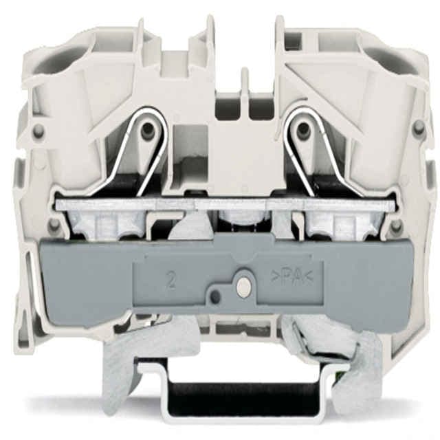
WAGO 2010-1208 shield terminal block is a 2-conductor, 10 mm² rail mount terminal block suitable for Ex e II applications.
Product Model2010-1208
Product ID40840
Stock on Request
Last updated: 8/29/2026
Key Features
1
{Point 1Suitable for Ex e II applications}, {Point 2: 2-conductor design}, {Point 3: 10 mm² width}, {Point 4: Side and center marking}, {Point 5: DIN-rail compatible (35 x 15 and 35 x 7.5)}
Technical Specifications
Detailed engineering parameters based on manufacturer documentation
Specifications may be subject to change without notice
Parameter
Value
Parameter
Value
Clamping units
2
Total number of potentials
1
Number of levels
1
Number of jumper slots
2
Width
10 mm / 0.394 inches
Height
67.8 mm / 2.669 inches
Depth from upper-edge of DIN-rail
36.9 mm / 1.453 inches
Mounting type
DIN-35 rail
Marking level
Center/side marking
Note (material data)
Information on material specifications can be found here
Color
white
Material group
I
Insulation material (main housing)
Polyamide (PA66)
Flammability class per UL94
V0
Fire load
0.256MJ
Weight
28.4g
Processing temperature
-35 … +85 °C
Continuous operating temperature
-60 … +105 °C
Product Group
22 (TOPJOB S)
eCl@ss 10.0
27-14-11-41
eCl@ss 9.0
27-14-11-41
ETIM 9.0
EC000901
ETIM 8.0
EC000901
ECCN
NO US CLASSIFICATION
PU (SPU)
25 pcs
Packaging type
box
Country of origin
DE
GTIN
4050821189138
Customs tariff number
8536904000
RoHS Compliance Status
Compliant,No Exemption
Ratings per
IEC/EN 60947-7-2
Connection technology
Push-in CAGE CLAMP®
Actuation type
Operating tool
Connectable conductor materials
Copper
Nominal cross-section
10 mm2
Solid conductor
0.5 16 m㎡/ 20 6 AWG
Solid conductor; push-in termination
4 16 m㎡/ 14 6 AWG
Fine-stranded conductor
0.5 16 m㎡/ 20 6 AWG
Fine-stranded conductor; with insulated ferrule
0.5 10 m㎡/ 20 8 AWG
Fine-stranded conductor; with ferrule; push-in termination
4 10 m㎡/ 12 8 AWG
Note (conductor cross-section)
Depending on the conductor characteristic, a conductor with a smaller cross-section can also be inserted via push-in termination.AWG specifications were converted according to IEC.
Strip length
17 19 mm / 0.67 0.75 inches
Wiring direction
Front-entry wiring
Test specification <br/>Railway applications <br/>Rolling stock <br/>Electronic equipment
DIN EN 50155 (VDE 0115-200):2022-06
Test procedure <br/>Railway applications <br/>Rolling stock equipment <br/>Shock and vibration tests
DIN EN 61373 (VDE 0115-0106):2011-04
Spectrum/Installation location
Service life test, Category 1, Class A/B
Function test with noise-like vibration
Test passed according to Section 8 of the standard
Frequency
f1= 5 Hz to f2= 150 Hz
Acceleration
5g (highest test level used for all axes)
Test duration per axis
5 h
Test directions
X, Y and Z axes
Monitoring for contact faults/interruptions
Passed
Voltage drop measurement before and after each axis
Passed
Simulated service life test through increased levels of noise-like vibration
Test passed according to Section 9 of the standard
Extended test scope: Monitoring for contact faults/interruptions
Passed
Extended test scope: Voltage drop measurement before and after each axis
Passed
Shock test
Test passed according to Section 10 of the standard
Shock form
Half sine
Shock duration
30 ms
Number of shocks per axis
3 pos. und 3 neg.
Vibration and shock stress for rolling stock equipment