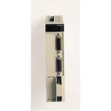
High-performance CPU unit for motion control and PLC applications.
Product ModelTSXCFY21
Product ID34953
Stock on Request
Last updated: 8/29/2026
Key Features
1
Advanced Motion ControlThe TSXCFY21 offers precise motion control functions, making it ideal for applications requiring simultaneous motion control by stepper motor and sequential control by PLC.
2
Integrated I/OsWith 2-axes integrated I/Os, this CPU unit simplifies system design and reduces the need for external I/O modules.
3
Robust Protection FeaturesEquipped with short-circuit protection, output overload protection, and reverse polarity protection, the TSXCFY21 ensures reliable operation in various industrial environments.
4
Easy DebuggingUtilize Unity Pro and PL7 Junior/Pro software for axis parameter setting and debugging, streamlining the development process.
5
Technical Specifications
Detailed engineering parameters based on manufacturer documentation
Specifications may be subject to change without notice
Parameter
Value
Parameter
Value
Range of Product
Modicon Premium Automation platform
Product or Component Type
Motion control module
Product Specific Application
For stepper motors
Software Designation
Unity Pro
I/O modularity
2 axes
Maximum pulse frequency
187 kHz
Versatile CommunicationCompatible with RS-422 protocol, this CPU unit facilitates seamless communication with various industrial devices, enhancing system integration and efficiency.
Power dissipation in W
5.6 W
Input type
Current sink auxiliary input EN/IEC 61131 type 2Resistive amplifier input
Discrete input logic
Negative amplifier inputPositive auxiliary input
Input voltage
24 V 7 mA auxiliary input5 V 4.5 mA amplifier input
Input voltage limits
19...30 V auxiliary input
Voltage state 1 guaranteed
< 2 V amplifier input>= 11 V auxiliary input
Current state 1 guaranteed
>= 6 mA auxiliary input)
Voltage state 0 guaranteed
<= 5 V auxiliary input> 3.6 V amplifier input
Current state 0 guaranteed
<= 2 mA auxiliary input)
Input impedance
3400 Ohm auxiliary input
Input immunity
< 250 µs auxiliary input for homing cam and event inputs15...30 µs amplifier input for loss of step input3000...10000 µs auxiliary input for limit switch, emergency stop and external stop inputs3000...16000 µs amplifier input for amplifier fault input
Power supply monitoring
0...14 V auxiliary input at fault state18...24 V auxiliary input at OK state
Maximum detection time
< 30 ms auxiliary input from fault to OK state> 1 ms auxiliary input from OK to fault state
Input compatibility
With 2-wire/3-wire sensor auxiliary input
Output type
Open collector PNP brake output EN/IEC 61131-2RS422, TTL 5 V open collector NPN compatible amplifier output
Output differential voltage
+/- 2 V <= 100 Ohm amplifier output
Maximum output short-circuit current
150 mA amplifier output
Permissible common mode voltage
7 V amplifier output
Maximum permissible differential voltage
12 V amplifier output
Output voltage
24 V DC 19...30 V brake output
Nominal output current
0.5 A <0.3 mA 0.625 A brake output
Maximum voltage drop
<1 V at state on brake output
Switching time
< 0.25 ms brake output
Output compatibility
Positive logic DC inputs (resistance <= 15 kOhm) brake output
Short-circuit protection
Thermal tripping via program or automatically brake output
Output overload protection
Current limiter brake output
Output overvoltage protection
Zener diode brake output
Reverse polarity protection
Brake output reverse mounted diode on supply
Speed profile path
Trapezoidal
Operating Mode
ManuallyAUTOOFFDirect drive mode
Checks
Sensor power supplyConsistency of commandsValidity of parametersShort circuit (one signalling bit per channel)Correct execution by software position limits, loss of stepAmplifier, limits switches, emergency stop
Optional commands
BrakeBoost
Local signalling
for module operating (RUN) 1 LED (green) for external fault (I/O) 1 LED (red) for internal fault, module failure (ERR) 1 LED (red) for axis diagnostics available (CH.) 2 LEDs (green)