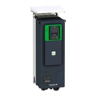
The ATV650U15N4EU is a versatile variable speed drive designed to optimize industrial processes with its adjustable speed control and robust protection features.
Product ModelATV650U15N4EU
Product ID29334
Stock on Request
Last updated: 8/29/2026
Key Features
1
Feature-
Technical Specifications
Detailed engineering parameters based on manufacturer documentation
Specifications may be subject to change without notice
Parameter
Value
Parameter
Value
Range of Product
Altivar Process ATV600
Product or Component Type
Variable speed drive
Product Specific Application
Process and utilities
Device short name
ATV650
Variant
With disconnect switch
Product destination
Asynchronous motorsSynchronous motors
EMC filter
Integrated 164.04 ft (50 m) IEC 61800-3 category C2Integrated 492.1 ft (150 m) IEC 61800-3 category C3
IP degree of protection
IP55IEC 60529IP55IEC 61800-5-1
[Us] rated supply voltage
380...480 V - 15...10 %
Degree of protection
UL type 12 UL 508C
Type of cooling
Forced convection
Supply frequency
50...60 Hz - 5...5 %
Motor power kW
0.75 kW heavy duty)1.5 kW normal duty)
Maximum Horse Power Rating
1 hp heavy duty2 hp normal duty
Line current
2.6 A 480 V normal duty)1.7 A 380 V heavy duty)1.5 A 480 V heavy duty)3 A 380 V normal duty)
Prospective line Isc
50 kA
Apparent power
1.2 kVA 480 V heavy duty)2.2 kVA 480 V normal duty)
Continuous output current
2.2 A 4 kHz heavy duty4 A 4 kHz normal duty
Asynchronous motor control profile
Constant torque standardOptimized torque modeConstant torque standard
Synchronous motor control profile
Synchronous reluctance motorPermanent magnet motor
Speed drive output frequency
0.1...500 Hz
Nominal switching frequency
4 kHz
Switching frequency
4...12 kHz with derating factor2...12 kHz adjustable
Slot A communication module, PROFINETSlot A communication module, DeviceNetSlot A communication module, Modbus TCP/EtherNet/IPSlot A communication module, CANopen daisy chain RJ45Slot A communication module, CANopen SUB-D 9Slot A communication module, CANopen screw terminalsSlot A/slot B digital and analog I/O extension moduleSlot A/slot B output relay extension moduleSlot A communication module, Ethernet IP/Modbus TCP/MD-Link communication module, BACnet MS/TP communication module, Ethernet PowerlinkSlot A communication module, Profibus DP V1
Mounting Mode
Wall mount
Maximum transient current
3.3 A 60 s heavy duty)4.4 A 60 s normal duty)
Phase
3 phase
Discrete output number
0
Discrete output type
Relay outputs R1A, R1B, R1C 250 V AC 3000 mARelay outputs R1A, R1B, R1C 30 V DC 3000 mARelay outputs R2A, R2C 250 V AC 5000 mARelay outputs R2A, R2C 30 V DC 5000 mARelay outputs R3A, R3C 250 V AC 5000 mARelay outputs R3A, R3C 30 V DC 5000 mA
Output voltage
<= power supply voltage
Permissible temporary current boost
1.5 x In 60 s heavy duty)1.1 x In 60 s normal duty)
Motor slip compensation
Automatic whatever the loadAdjustableCan be suppressedAdjustable
Acceleration and deceleration ramps
Linear adjustable separately from 0.01...9999 s
Physical interface
Ethernet2-wire RS 485
Braking to standstill
By DC injection
Protection type
Safe torque off motorMotor phase break motorThermal protection driveSafe torque off driveOverheating driveOvercurrent between output phases and earth driveOverload of output voltage driveShort-circuit protection driveMotor phase break driveOvervoltages on the DC bus driveLine supply overvoltage driveLine supply undervoltage driveLine supply phase loss driveOverspeed driveBreak on the control circuit driveThermal protection motor
Line side screw terminal 4...6 mm²Motor screw terminal 4...6 mm²Control removable screw terminals 0.5...1.5 mm²
Connector type
RJ45 on the remote graphic terminal)Modbus serialRJ45 on the remote graphic terminal)Ethernet/Modbus TCP
Data format
8 bits, configurable odd, even or no parity
Type of polarization
No impedance
Exchange mode
Half duplex, full duplex, autonegotiation Ethernet/Modbus TCP
Number of addresses
1...247 Modbus serial
Method of access
Slave Modbus TCP
Supply
Internal supply for reference potentiometer (1 to 10 kOhm) 10.5 V DC +/- 5 %, <10 mA overload and short-circuit protectionInternal supply for digital inputs and STO 24 V DC 21...27 V), <200 mA overload and short-circuit protectionExternal supply for digital inputs 24 V DC 19...30 V), <1.25 mA overload and short-circuit protection
Local signalling
for embedded communication status 3 LEDs (dual colour) for communication module status 4 LEDs (dual colour) for presence of voltage 1 LED (red) for local diagnostic 3 LEDs
Width
10.4 in (264 mm)
Height
26.7 in (678 mm)
Depth
11.8 in (300 mm)
Net Weight
23.1 lb(US) (10.5 kg)
Analogue input number
3
Analogue input type
AI1, AI2, AI3 software-configurable voltage 0...10 V DC 31.5 kOhm 12 bitsAI1, AI2, AI3 software-configurable current 0...20 mA 250 Ohm 12 bitsAI2 voltage analog input - 10...10 V DC 31.5 kOhm 12 bits
Discrete input number
8
Discrete input type
DI7, DI8 programmable as pulse input 0...30 kHz, 24 V DC <= 30 V)
Software-configurable voltage AQ1, AQ2 0...10 V DC 470 Ohm 10 bitsSoftware-configurable current AQ1, AQ2 0...20 mA 10 bitsSoftware-configurable current DQ-, DQ+ 30 V DCSoftware-configurable current DQ-, DQ+ 100 mA
Sampling duration
5 ms +/- 1 ms DI5, DI6) - discrete input5 ms +/- 0.1 ms AI1, AI2, AI3) - analog input10 ms +/- 1 ms AO1) - analog output2 ms +/- 0.5 ms DI1...DI4) - discrete input
Accuracy
+/- 1 % AO1, AO2 for a temperature variation 60 °C analog output+/- 0.6 % AI1, AI2, AI3 for a temperature variation 60 °C analog input
Linearity error
AO1, AO2 +/- 0.2 % analog outputAI1, AI2, AI3 +/- 0.15 % of maximum value analog input
Relay output R1, R2, R3 resistive, cos phi = 1 3 A 30 V DCRelay output R1, R2, R3 inductive, cos phi = 0.4 7 ms 2 A 250 V ACRelay output R1, R2, R3 inductive, cos phi = 0.4 7 ms 2 A 30 V DCRelay output R1, R2, R3 resistive, cos phi = 1 3 A 250 V AC
Isolation
Between power and control terminals
Maximum output frequency
500 kHz
Maximum Input Current per Phase
3.0 A
Quantity per Set
1
enclosure mounting
Wall mounted
Insulation resistance
> 1 MOhm 500 V DC for 1 minute to earth
Noise level
52 dB
Operating position
Vertical +/- 10 degree
Maximum THDI
<48 % full load IEC 61000-3-12
Electromagnetic compatibility
Radiated radio-frequency electromagnetic field immunity test level 3 IEC 61000-4-3Electrical fast transient/burst immunity test level 4 IEC 61000-4-41.2/50 µs - 8/20 µs surge immunity test level 3 IEC 61000-4-5Conducted radio-frequency immunity test level 3 IEC 61000-4-6Electrostatic discharge immunity test level 3 IEC 61000-4-2
Pollution degree
3
Vibration resistance
1 gn 13...200 Hz)IEC 60068-2-61.5 mm peak to peak 2...13 Hz)IEC 60068-2-6
Shock resistance
15 gn 11 ms IEC 60068-2-27
Relative humidity
5...95 % without condensation IEC 60068-2-3
Ambient air temperature for operation
104...122 °F (40...50 °C) with derating factor)5...104 °F (-15...40 °C) without derating)
Ambient Air Temperature for Storage
-40...158 °F (-40...70 °C)
Operating altitude
1000...4800 m with current derating 1 % per 100 m<= 3280.84 ft (1000 m) without derating