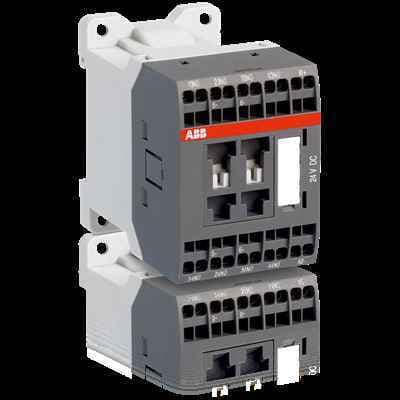
The ABB NSL31ES-81 is a 24VDC contactor relay, engineered for reliability and efficiency. It is designed for various applications, ensuring smooth and consistent operation.
Product ModelNSL31ES-81
Material Number1SBH103004R8131
Product ID110418
Stock on Request
Last updated: 8/29/2026
Key Features
1
1. Reliability and EfficiencyThe ABB NSL31ES-81 contactor relay is built to last, providing reliable performance in a wide range of applications. Its efficient design ensures smooth and consistent operation, reducing downtime and increasing productivity.
2
2. Versatile ApplicationsThis contactor relay is versatile and can be used in various electrical systems, including industrial automation, HVAC, and more. Its adaptability makes it a go-to solution for diverse applications.
3
3. High-Quality ConstructionConstructed with high-quality materials, the NSL31ES-81 contactor relay is designed to withstand the rigors of continuous use. Its robust build ensures long-lasting performance and minimal maintenance.
4
4. Easy InstallationThe ABB NSL31ES-81 is designed for easy installation, making it a convenient choice for electrical engineers and technicians. Its straightforward setup ensures quick integration into existing systems.
Technical Specifications
Detailed engineering parameters based on manufacturer documentation
Specifications may be subject to change without notice
Parameter
Value
Parameter
Value
Product Net Width
45 mm
Product Net Depth / Length
72.5 mm
Product Net Height
68 mm
Product Net Weight
0.28 kg
Number of Auxiliary Contacts NO
3
Number of Auxiliary Contacts NC
1
5
5. Compliance with Industry StandardsThe contactor relay meets and exceeds industry standards for safety and performance. It is compliant with relevant regulations, providing peace of mind for users in terms of safety and reliability.
Standards
IEC 60947-5-1 and EN 60947-5-1, UL 508, CSA C22.2 N°14
Rated Operational Voltage
Auxiliary Circuit 690 V Main Circuit 690 V
Rated Frequency (f)
Auxiliary Circuit 50 / 60 Hz
Conventional Free-air Thermal Current (Ith)
acc. to IEC 60947-5-1, Π= 40 °C 10 A
Rated Operational Current AC-15 (Ie)
(500 V) NC 2 (500 V) 2 A (690 V) 2 A (24 / 127 V) 6 A (220 / 240 V) 4 A (400 / 440 V) 3 A
Rated Short-time Withstand Current Low Voltage (Icw)
for 0.1 s 140 A for 1 s 100 A
Maximum Electrical Switching Frequency
(AC-15) 1200 cycles per hour (DC-13) 900 cycles per hour
Rated Operational Current DC-13 (Ie)
(24 V) 6 A / 144 W (48 V) 2.8 A / 134 W (72 V) 1 A / 72 W (110 V) 0.55 A / 60 W (125 V) 0.55 A / 69 W (220 V) 0.27 A / 60 W (250 V) 0.27 A / 68 W
Rated Insulation Voltage (Ui)
acc. to IEC 60947-5-1 and VDE 0110 (Gr. C) 690 V acc. to UL/CSA 600 V
Rated Impulse Withstand Voltage (Uimp)
Auxiliary Circuit 6 kV
Maximum Mechanical Switching Frequency
3600 cycles per hour
Rated Control Circuit Voltage (Uc)
DC Operation 24 V
Operate Time
Between Coil De-energization and NC Contact Closing 15 ... 20 ms Between Coil De-energization and NO Contact Opening 13 ... 17 ms Between Coil Energization and NC Contact Opening 31 ... 53 ms Between Coil Energization and NO Contact Closing 36 ... 59 ms
acc. to IEC 60529, IEC 60947-1, EN 60529 Auxiliary Terminals IP20 acc. to IEC 60529, IEC 60947-1, EN 60529 Coil Terminals IP20
Terminal Type
Spring Terminals
Ambient Air Temperature
Close to Contactor for Storage -60 ... +80 °C Near Contactor for Operation in Free Air -40 ... 70 °C
Climatic Withstand
Category B according to IEC 60947-1 Annex Q
Maximum Operating Altitude Permissible
Without Derating 3000 m
Resistance to Shock acc. to IEC 60068-2-27
Closed, Shock Direction: A 20 g Closed, Shock Direction: B1 15 g Closed, Shock Direction: C1 19 g Closed, Shock Direction: C2 14 g Open, Shock Direction: A 10 g Open, Shock Direction: B1 5 g Open, Shock Direction: C1 8 g Open, Shock Direction: C2 8 g Shock Direction: B2 10 g
Resistance to Vibrations
3g Closed Position & 2g Open Position 5 ... 300 Hz